


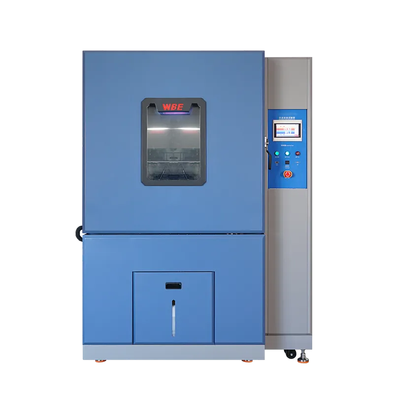
A rapid rate temperature exchange chamber does not invent new failure mechanisms. It compresses the time axis of mechanisms that were always there, which is why a part that survived years in the field can crack in a week on the bench. We have opened chambers after a long cycling programme and found solder joints that looked intact at low magnification and were already partly separated under a microscope. Nothing about the assembly was defective. The profile had simply run enough cycles, at a swing wide enough, to accumulate damage the real duty cycle would have taken years to reach.
This guide explains the physics in the order that actually helps an engineer choose a profile. We will cover five things in sequence: where the defect physically lives, how a temperature change turns into stress, how a fatigue model turns cycles into a predicted life, why rate can expose more than cycle count alone, and what the equipment must deliver to reproduce all of it. Once you can name the mechanism, the chamber specification stops being a list of numbers and becomes a set of requirements.
The short version, if you only read this far
- Cracks begin where two materials with different expansion meet, and the corner of a joint sees the highest strain.
- Damage per cycle grows faster than the temperature swing, so the exponent is the whole story.
- A fast transition denies creep the time it needs to relax stress, so peak strain per cycle rises.
- Electrical continuity usually outlives the crack, so inspection is part of the test, not an extra.
Step 1: Locate Where the Defect Actually Lives
Every hidden thermal defect starts at an interface between two materials, so the first job is to name which interface you are hunting. Cycling a whole assembly and then discovering you stressed the wrong bond wastes the programme budget and the calendar, and it happens because teams start from a profile instead of from a failure location. We always ask three questions before recommending anything: what fails, where does it fail, and does the field produce that failure slowly or suddenly.
| Interface | What it connects | How the crack shows itself |
|---|---|---|
| Solder joint | Package terminal to board pad | Starts at the joint corner and grows inward, continuity holds for a long time |
| Bond or die attach | Wire to pad, or die to substrate | Lifts or fatigues with no external mark, so a pull or shear test finds it first |
| Interlayer interface | Layer to layer inside a board or laminate | Barrel or via cracking driven by through thickness expansion |
| Contact interface | Connector or press fit to its housing | Slow fretting and resistance creep rather than a clean break |
The practical point is that different interfaces fail on different curves, and a profile tuned for one will under-load another. A programme chasing barrel cracking needs a different emphasis from one chasing a die attach layer, even though both sit on the same board. Once you know which interface you are targeting, the next question is how a temperature change turns into force at that interface.
Step 2: How a Temperature Change Becomes Stress
Heat makes materials grow, and different materials grow by different amounts for the same temperature change; that mismatch is the whole engine of thermal fatigue. The number that describes how much a material grows per degree is its coefficient of thermal expansion, usually shortened to CTE. When two materials with different CTE values are bonded together, the pair cannot both have their way, so something has to give, and that something is the joint between them.
Put it in plain terms. A ceramic package barely moves when it gets hot, while the organic board under it expands a good deal more. The solder that holds them together is caught in the middle, and it absorbs the difference as shear, cycling one way on the way up and the other way on the way down. The joint is not being pulled apart by one big force; it is being worked back and forth, thousands of times, which is exactly what fatigue means.
- Strain scales with the mismatch. The further apart two CTE values are, the more the joint has to absorb for the same swing.
- Strain scales with the temperature swing. A wider excursion moves both materials further, so the joint travels further too.
- Strain scales with distance from the neutral point. That is why the corner of a joint carries the most, and why cracks begin there.
- Strain lands on the weakest link. Whichever element is most compliant takes the motion, so the soft layer survives while a brittle interface fails.
In practice you rarely get to change the materials, so the swing and the geometry do the work, and the swing is the variable you control from the test bench. That is also why the failure is so quiet. Electrical continuity frequently holds long after a fatigue crack has started, so a functional check at the end of a run can happily pass a part that is already on its way to failing in the field. Now that we know how the stress arrives, the next question is how many repetitions of it a joint can take.
Step 3: How Coffin-Manson Turns Cycles Into Life
The Coffin-Manson relationship is an empirical model: it says that fatigue life in a cyclically strained joint falls as a power function of the inelastic strain range, and that strain range rises with the temperature swing. Empirical means it was fitted to experiment rather than derived from first principles, so it is a tool for comparing profiles and predicting trends, not a law of nature and not a source of exact cycle counts for your specific board.
What the exponent actually means
The model can be summarised as life being inversely proportional to the strain range raised to some exponent, and that exponent is the part worth remembering. When the exponent is greater than one, doubling the swing does not double the damage, it multiplies it, so modest looking increases in temperature difference can cut cycles to failure by far more than intuition suggests. We deliberately do not quote a coefficient here, because the value depends on the alloy, the joint geometry and the cycle shape, and a number lifted from a different assembly would be worse than none at all.
Two corrections matter in a real programme. The first is time: the model assumes a cycle shape, and if your transitions are much faster or much slower than the one it was fitted to, the prediction drifts. The second is the mean temperature, because the same swing centred on a hot condition usually costs more life than the same swing centred on a cold one. That is why we ask for the complete profile, including dwell lengths and ramp times, rather than a single swing figure, before we discuss any chamber configuration.
Why this shapes the equipment choice
If damage climbs steeply with swing and cycle count, then the two numbers that decide whether a programme is meaningful are the swing you can actually reach inside a loaded workspace, and the number of cycles you can finish in a realistic window. That is exactly the conversation we have when a team moves from a general purpose cycling unit to a dedicated rapid temperature change test chamber. The question is never only how cold it gets. It is how fast it gets there with product inside, and how little recovery time it needs before the next cycle begins. With the life model in hand, the next thing to settle is why rate matters as much as the count.
Step 4: Why Fast Exposes More Than Many
A fast transition exposes defects that a slow one hides, because slowing the change gives time dependent processes the time they need to relax the stress away. Creep, stress relaxation and the slow redistribution of load across a joint are all time dependent, so when a transition finishes quickly those processes never complete, and the joint carries a higher peak strain for a shorter fraction of each cycle. The mechanisms do not change with rate; their relative importance does.
| Mechanism | What drives it | What a short transition changes |
|---|---|---|
| Solder joint fatigue | Swing, mismatch, cycle count | Less creep relaxation per cycle, so peak strain rises |
| Bond or die attach fatigue | Interface quality and mismatch | Sharper internal gradients load the interface unevenly |
| Barrel or via cracking | Board thickness and expansion in the Z axis | Faster through thickness gradient between hole and board |
| Connector and press fit wear | Relative motion at the contact | More motion per cycle before the joint settles |
Read the third column as a single idea: a fast ramp removes the cushion. It also shortens the dwell, and dwell length is a real variable rather than dead time. A long soak lets a marginal interface relax and partially recover, which is precisely why a slow profile can pass a joint that will separate quickly in a colder, faster real environment. There is a window here rather than a straight line, because very fast cycling with very short dwells changes which process dominates, so the answer is to match the profile to the mechanism you fear rather than to assume faster is always harsher.
One lab we work with found this the hard way with a consumer assembly. They were qualifying a handset build and could not decide whether a faster platform was worth it, because their existing cycling profile took weeks per lot and only ever covered the first build. We ran a paired comparison on a platform with controlled ramp behaviour, and the honest result was not that the fast profile found a different defect. It found the same defect class in a fraction of the calendar time, which changed how many builds could be covered before the design froze. For a programme like that, the value of the equipment is measured in coverage rather than in stress.
That is the physics settled. What remains is to check that the machine on your bench can actually reproduce it, because a rate specified on a datasheet and a rate delivered inside a loaded workspace are two different claims.
Step 5: What a Rapid Rate Temperature Exchange Chamber Must Deliver
To reproduce this physics, a rapid rate temperature exchange chamber has to hold a rate with the load in place, hold uniformity across the workspace, and recover fast enough that cycle count is not eaten by dead time. Four specifications carry that load, and they are the ones we publish because they are the ones we commission against.
- Rate steps of 5, 10, 15, 20 and 25 °C/min, so the profile can be tuned to the mechanism instead of being forced into whatever the machine happens to do.
- Both linear and average non-linear modes. Linear means the rate is held all the way through the transition; average non-linear means the figure is an average over the whole move, with faster and slower portions inside it. For fatigue work the difference is not cosmetic, because the peak rate is what loads the joint hardest.
- Uniformity of 1.5 °C or better, so every position in the load sees a similar swing, and the sample that fails is not simply the one nearest the air outlet.
- Optional liquid nitrogen, humidity and anti-condensation. Liquid nitrogen buys the deepest and fastest cooling, humidity adds a corrosion or moisture path to the sequence, and the anti-condensation design keeps condensate from dripping onto the samples and changing the result.
The airflow layout matters as much as the headline rate. Our platforms use a top air outlet and a bottom return path, which keeps the flow predictable once a load is present, and that is what makes the 1.5 °C uniformity figure meaningful in a real test rather than in an empty chamber. Programmes that need a controlled ramp for solder fatigue usually centre the bench on a linear ramp rapid temperature change chamber, while teams that need the highest cycle count per week lean on a temperature cycling chamber with a defined ramp rate.
Where the target defect is closer to the package than the board, the same logic applies on a different platform. Semiconductor and packaging teams add traceability of the thermal history per unit rather than per batch, and that work is described on our semiconductor application page. On the consumer side, where thin form factors and drop loads sit alongside thermal cycling, the arrangements we see most often are covered under 3C and 6C applications. If you are still weighing whether rapid change is even the right instrument, the comparison between a rapid change chamber and a temperature cycling chamber is worth reading before you specify anything.
Frequently Asked Questions
Does a wider swing always shorten life more?
For a pure fatigue mechanism, yes, because damage per cycle scales with the swing raised to an exponent above one. But the mean temperature and the cycle shape matter too, and a hot centred swing is usually more damaging than a cold centred one of the same width. That is why we ask for the whole profile before recommending a platform.
Why does a rapid rate temperature exchange chamber find what a slow profile misses?
Because a slow transition gives creep and stress relaxation the time to reduce peak stress, so a joint that is marginal rather than broken can survive it. If the field changes temperature quickly, a slow bench test exercises a different mechanism and reports a pass that means little. Rate and swing are separate variables, and a test only covers the one it actually applies.
Do we need to inspect samples for the test to be meaningful?
Yes, and this is the step most programmes skip. Electrical continuity frequently survives long after a fatigue crack has initiated, so a functional pass at end of test proves very little about the interface. Where the crack started is the single most informative measurement you can make, and it often redirects the investigation immediately.
Is faster always better for qualification work?
No. Speed buys coverage, which is genuinely valuable, but only if the mechanism you accelerate is the mechanism that will fail. A fast profile aimed at the wrong interface produces impressive looking damage that has nothing to do with the field failure, and the programme then spends its remaining budget explaining that away.
The physics behind a rapid rate temperature exchange chamber is old and well documented: mismatched expansion creates strain, cycling accumulates damage, and the accumulation punishes wide swings and high cycle counts. What changes when the machine lands on your bench is not the physics but the feedback loop. You stop arguing about which mechanism is plausible and start looking at where the crack actually started. Read the sample, name the mechanism, then set the profile, and the equipment stops being a stress generator and becomes an instrument for answering one specific question.
Stress the mechanism, not just the sample
Look through rapid change platforms built for high cycle counts and controlled ramp behaviour, listed by chamber construction and controller options so you can match the equipment to the failure you are chasing.
Compare rapid exchange platforms Describe the failure you are chasing